Using TikZ with sketch
In a previous post I introduced TikZ, a powerful LaTeX package that helps you create high quality drawings that can be directly incorporated into LaTeX documents. TikZ itself is highly suited for creating simple 1D and 2D diagrams (granted, the 2D case is much more likely), and it is very easy to write (Python) scripts that can generate the TikZ code for more complicated 2D drawings, like the ones in this post. However, TikZ is a bit harder to use for 3D drawings, and this is where this week’s post fits in.
The main problem with 3D drawings is depth perception. When you project a 3D scene onto a 2D plane (the drawing), you loose the third dimension (duh!) and with it the feeling of which objects are in the front and which ones are in the back. There are a number of ways of mimicking this feeling in a 2D drawing of a 3D object. A first way is to make your projection preserve some of the properties of a real 3D space, e.g. the property that an observer perceives objects that are far away as being smaller than ones that are closer by. This is fine for scenes that contain regular objects over a wide enough range of distances, but does not really help if you are visualising a shape that is not known to the person that looks at your image, which is often the case for a technical drawing. This does not mean you should not use a projection algorithm that makes distant objects smaller; it simply means it is not always enough to add depth perception to your scene.
Another interesting property of 3D spaces is the fact that distant objects are completely or partially hidden by objects in the foreground. You can mimic this property by not drawing objects that are covered by foreground objects, or by drawing them differently, e.g. as dashed lines instead of full lines. This sounds easy, but is actually pretty tricky to do: you need to order all objects in the scene according to their distance to the observer (i.e. a specific point in the space that acts as a virtual eye that observes the scene) and then use that information when you draw the objects in the scene. Most computer algorithms that do this (and there are many, both in the gaming industry, design, 3D rendering sector…) use a surprisingly simple approach: they order the objects in a so called depth buffer and then draw them one by one, starting from the deepest object (furthest away). Objects that are drawn later automatically cover objects that were drawn before, and hence naturally satisfy the real 3D space property.
So adding depth perception is conceptually not hard: it simply requires you to order your objects and then draw them in a specific order. Doing this in practice is a bit more tricky, as ordering objects is not as easy as it sounds, especially if you do it manually. Furthermore, it does not necessarily always work: what happens for example if multiple objects are nested in 3D space, so that part of object A is in front of object B, while another part is behind?
In conclusion: drawing even simple 3D scenes in plain TikZ can be very complicated, and writing a (Python) script that generates 3D TikZ requires you to worry about a lot of things you would not normally want to worry about. Would it not be helpful if there was a tool that can simply things for you?
Sketch
This is where sketch enters the equation. sketch is a bit sketchy (pun intended, sorry about that) in the sense that is not very widely used, and its online documentation is quite limited. You probably need to install it manually, as last time I checked it was not part of any standard Linux distribution. Yet despite all this, sketch is quite easy to use and surprisingly powerful.
In essence, sketch is a tool that allows you to create your 3D scene in a way that is very similar to the way you create 2D scenes in TikZ, and then automatically converts that scene into a 2D TikZ drawing, by using appropriate projections. The idea is that you write your 3D scene into a file (with a conventional .sk extension) using sketch’s own description language. You then convert this file into a regular TikZ .tex file using the sketch command line tool, include the resulting tikzpicture into a skeleton TikZ .tex file, and convert that into an image using the regular TikZ methods. As before, the .sk file can be generated by a (Python) script, allowing for the creation of arbitrarily complicated 3D scenes.
An example
Below is a skeleton scene.sk file that draws a cube, a line and a dot:
def p000 (0, 0, 0)
def p001 (0, 0, 1)
def p010 (0, 1, 0)
def p011 (0, 1, 1)
def p100 (1, 0, 0)
def p101 (1, 0, 1)
def p110 (1, 1, 0)
def p111 (1, 1, 1)

polygon(p000)(p001)(p011)(p010)
polygon(p100)(p101)(p111)(p110)
polygon(p000)(p001)(p101)(p100)
polygon(p010)(p011)(p111)(p110)
polygon(p000)(p010)(p110)(p100)
polygon(p001)(p011)(p111)(p101)

line(0.5, 0.5, -1)(1.5, 1.5, 1.5)

dots(1, 1, 1)

global { language tikz }
The syntax might seem a bit odd at first, but is relatively easy to learn. First of all, the def lines store the locations in space (e.g. (0, 0, 0)) into variables with unique labels (note that labels have to be unique). These positions are then used to generate 6 polygons, corresponding to the 6 faces of the cube. Next, we draw a line in between the two given positions. We finish by drawing a dot (dots) at the given location. The final line guarantees that sketch generates TikZ output.
Note that sketch does not actually allow you to draw complicated 3D objects like cubes, but instead requires you to draw the individual faces of these objects. The reason for this is simple: you can use polygons to construct the faces of pretty much any object, while individual 3D objects would be pretty limited in their use. The sketch language only provides basic 3D constructs, if you want to define more complicated objects, you will need to write a higher level wrapper script.
To convert scene.sk into an actual image, we first need to run sketch:
> sketch -o scene_sk.tex scene.sk
This will generate a new file, scene_sk.tex, with the TikZ output of the 2D projection. Note that you might need to specify the full path to the sketch executable for this to work. The output file can be included in a skeleton LaTeX file, scene.tex:
\documentclass[convert={density=300,outext=.png}]{standalone}
\usepackage{tikz}
\begin{document}
\input{scene_sk}
\end{document}
And rendered into an image:
> pdflatex -shell-escape scene.tex
The resulting image looks like this:
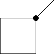
As you can see, the scene does not look very 3D. The reason for this is that the default viewing direction for any sketch drawing is along the z axis, and the only real 3D object in our scene (the cube) has four faces aligned with this axis, that hence do not show up. We can improve on this by explicitly defining an observer position:
def p000 (0, 0, 0)
def p001 (0, 0, 1)
def p010 (0, 1, 0)
def p011 (0, 1, 1)
def p100 (1, 0, 0)
def p101 (1, 0, 1)
def p110 (1, 1, 0)
def p111 (1, 1, 1)

def pol0 polygon(p000)(p010)(p011)(p001)
def pol1 polygon(p100)(p110)(p111)(p101)
def pol2 polygon(p000)(p001)(p101)(p100)
def pol3 polygon(p010)(p011)(p111)(p110)
def pol4 polygon(p000)(p100)(p110)(p010)
def pol5 polygon(p001)(p101)(p111)(p011)

def cube0 { {pol0}{pol1}{pol2}{pol3}{pol4}{pol5} }

def line0 line(0.5, 0.5, -1)(1.5, 1.5, 1.5)

def dot0 dots(1, 1, 1)

def eye (20.0, 10.0, 15.)
def look_at (0.0, 0.0, 0.0)
put {view((eye), (look_at))} { {cube0}{line0}{dot0} }

global { language tikz }
As you can see, we now wrapped all objects into variables and then put the entire scene (consisting of all these objects) into a view observed by a virtual observer at position eye looking at position look_at. The scene now renders as
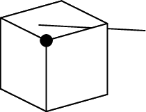
The 3 hidden faces of the cube are now properly concealed, and the part of the line passing through the cube is hidden as it should as well.
Before I move on, I need to point out that the order of the vertices in the polygon calls matters a lot for the result of this drawing. By default, sketch culls polygons that have their surface normal oriented away from the observer. Or in other words, it assumes that these faces are not visible and removes them from the drawing. If you were to swap p010 and p001 in the pol0 define for example, that face would no longer show up, even when it is not hidden by other faces. If you want to switch off this default behaviour, you have to add an additional cull=false argument to the polygon construction:
def pol0 polygon[cull=false](p000)(p001)(p011)(p010)
Showing hidden objects
The example above works, but does not contain all the information in the original drawing: we can assume we see a cube, but we might just as well be showing a pyramid from exactly the right angle so that it looks like a cube.
We can make the hidden faces show up in a different line style, so that it is clear they are concealed, but so that they are still visible. To do this, we need to use a trick. By default, sketch hides objects that are not visible. We can switch this behaviour off by adding a [lay=over] argument to the object. This way, the object will always be drawn, even when it should be hidden. If we now draw the same object twice, once in the normal style that should be used when it is visible, and once in the special style that should be used when it is not, then the normal style will hide the special style when the object is visible, while the special style will still be visible when the normal style is hidden. The relevant change to our example is
def dpol0 polygon[lay=over,fill style=fill=none,line style=dotted]
  (p000)(p010)(p011)(p001)
def dpol1 polygon[lay=over,fill style=fill=none,line style=dotted]
  (p100)(p110)(p111)(p101)
def dpol2 polygon[lay=over,fill style=fill=none,line style=dotted]
  (p000)(p001)(p101)(p100)
def dpol3 polygon[lay=over,fill style=fill=none,line style=dotted]
  (p010)(p011)(p111)(p110)
def dpol4 polygon[lay=over,fill style=fill=none,line style=dotted]
  (p000)(p100)(p110)(p010)
def dpol5 polygon[lay=over,fill style=fill=none,line style=dotted]
  (p001)(p101)(p111)(p011)
def pol0 polygon(p000)(p010)(p011)(p001)
def pol1 polygon(p100)(p110)(p111)(p101)
def pol2 polygon(p000)(p001)(p101)(p100)
def pol3 polygon(p010)(p011)(p111)(p110)
def pol4 polygon(p000)(p100)(p110)(p010)
def pol5 polygon(p001)(p101)(p111)(p011)

def cube0 { {dpol0}{dpol1}{dpol2}{dpol3}{dpol4}{dpol5}
            {pol0}{pol1}{pol2}{pol3}{pol4}{pol5} }
The lay=over was already introduced above, the fill style and line style attributes make sure the polygon face is transparent (only the contours are drawn) and the contour lines are dotted. The example also shows that sketch allows you to break up long lines. The resulting image is shown below:
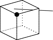
The hidden lines are now shown and we can see we are really drawing a cube.
More later
The examples in this post give a very minimal overview of the capabilities of sketch. In the next post, I will introduce more advanced capabilities, like additional styling, text labels, colours… and show you how to duplicate and move parts of the drawing to make more complicated diagrams.
Professional astronomer.